Subaru Impreza GC8 & RS Forum & Community banner

DIY: Reprogram the Odometer on your Swapped Dash

1 reading
224K views 192 replies 61 participants last post by  jegfaller  
#1 · (Edited by Moderator)
Warning! Modification of a vehicle odometer for fraudulent purposes is against the law! Check your local laws before proceeding. Make sure you have contacted your local law enforcement and government for additional steps, licenses, forms, etc. required to complete this procedure legally.

This guide is aimed at individuals who have swapped in different digital gauge clusters and would like to match their odometer to the actual mileage of their vehicle. I will be focusing on the V5/6 cluster with the solid PCB. I haven’t handled a soft-back V4 cluster so I cannot comment on the differences. Newer clusters from a GD should be the same as a V5/6, but I cannot confirm yet.

This modification is a little on the difficult side. You should be proficient at soldering and have a general understanding of electronics, programming and hexadecimal math.

I have not perfected the math for coding the odometer chip. While I can get the mileage close, I cannot program the chip exactly to some numbers.

Required Tools:
  • Flat head screwdriver
  • Soldering Iron and solder
  • De-soldering tools: Copper braid or a solder-vacuum
  • Pliers
  • A pen
  • Personal computer with a serial port
  • Microwire serial programmer (schematic included)
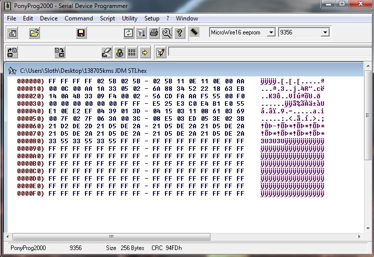
  • Serial programming software (Such as PonyProg2000: PonyProg - Serial device programmer )

Step 1: Extraction.

The first step is to remove the odometer memory chip from the gauge cluster. This is the most difficult part of the entire project. Start with a cluster removed from your car. I won’t cover removing the gauge cluster.

Remove the rear plastic cover by lifting the ten tabs around the side, and pressing back on the three ‘center’ tabs on the back. A slotted screwdriver helps with this.
Image


Once you have removed the rear cover, you now have to free the stepper motors from the PCB. Locate the four motors. I have circled them in the picture. Using the screwdriver and the pliers, pry back the two tabs on each motor. Be careful not to scratch any traces nearby.
Image


Using a ballpoint pen, push gently on each motor, pushing it away from the board. This is to free the motors a little so they come off easily when you remove the PCB.

Remove the circuit board. You may have to push back the three plastic tabs. If the stepper motors are still stuck onto the board, you can try wiggling the board a bit or push the motors away with a pen.

Once the board is free from the rest of the gauge cluster, you can start to remove the odometer memory chip. First locate the chip. I have circled here in the picture.
Image

Image


In most cases it should be a 93C56EN. You must now de-solder the chip. There are eight connections to the PCB. I have marked the points in the picture. I used a solder vacuum, but use whatever you are most comfortable with.

Once you have the extracted chip, you can start with the programmer.
 
#2 · (Edited)
Step2: Programmer.

Shown here is one of the most simplistic Microwire serial programmers one can build.
Image


The following components are used:

  • 3x 5v Zener diodes
  • 3x 4.7k ohm resistors
  • 2x 47uF electrolyte capacitors
  • 2x 100 mF ceramic capacitors
  • 3x high-speed diodes (1N4148)
  • 1x 5 volt regulator, suggested LM2936Z
  • 1x 8-pin DIP socket
  • 1x DB9 male serial jack

My completed programmer looks something like this:
Image


Step 3: Decoding.

Install and launch PonyProg2000.
From the SetUp menu, choose Interface Setup.

You should have the I/O port set as:
  1. Serial
  2. SI Prog I/O
  3. Which ever port you connected you programmer to.
  4. Leave all the check boxes unchecked.
Click OK!

From the chipset dropdown, choose MicroWire 16 eeprom and the 9356 chip.

Insert your odometer chip into the programmer, and connect the programmer to your computer.

From the command menu, click the Read option.
You should now be presented with a memory dump of your odometer chip.
Image
 
#3 · (Edited)
Step 4: Encode Chip

Looking at the memory dump from your odometer chip, the lines we are interested in are 000060 and 000070.

The mileage is encoded in two hexadecimal octets. The two octets have an inverted checksum.
These four octets are duplicated four times per line, for a total of eight copies.

In my case, I have 20 1B DF E4 duplicated eight times.
My actual mileage is contained in 20 1B. The DF E4 is the inverted checksum.

Each digital is a multiplier.
  • The first digit is a 65,536 multiplier.
  • The second digit is a 4,096 multiplier.
  • The third digit is a 256 multiplier.
  • I haven’t quite figured out the fourth digit, it appears to loop based on an extra multiplier.

So far I can’t figure out how to get even numbers on the odometer. If others would like to post up their mileage, let’s see if we can figure out exactly how to encode the values.

I haven't figured out the details, but the following table appears to work well enough:
Code:
0 = 15
1 = 95
2 = 223
3 = 143
4 = 159
5 = 207
6 = 79
7 = 31
8 = 191
9 = 239
A = 111
B = 63
C = 47
D = 127
E = 255
F = 175
In my case, 20 1B can be read as (2 x 65536) + (0 x 4096) + (1 x 256) + 63 which equals 131391!

Let’s say I want to change my mileage to 203,151. I would use 31 93.
(3 x 65536) + (1 x 4096) + 91 x 256) + 143 = 203151.

The checksum is found by inverting each digit.
In my case I get 31 93 CE 6C


For ease, the checksums can be found using this table:
Code:
0 - F
1 - E
2 - D
3 - C
4 - B
5 - A
6 - 9
7 - 8
8 - 7
9 - 6
A - 5
B - 4
C - 3
D - 2
E - 1
F - 0
 
#4 · (Edited)
Once you have your new value to encode, enable the Edit Buffer in PonyProg from the Edit menu. Click on each octet and make your changes.
Remember to repeat your value and checksum four times per line!

When done, issue a write command; select Write All from the Command menu.
To be on the safe side, verify that the write is correct, select Verify All from the Command menu.

If everything is good so far, it’s time to finish up.

You can now reinsert the chip into the gauge cluster and solder all eight points.
Reassembly is the reverse of disassembly.
 
#14 ·
Confused at to whether you are using the serial connection and the adapter or just the serial connection?

Need more input.
I am technically using serial, however I am also sinking power from the serial lines. You need the 'programmer' to power the serial eeprom and to protect the PC.

I am an ELET at LaTech and we are just now starting this... >_< this is quite facinating.. I love it...

I must say that is some good work.
Thanks! I have zero electrical education, I've just figured things out as I went.
Perhaps you could help me decode a few dumps to see if we can figure out the rest of the logic. I still can't get even numbers...

OK so when can we send you our clusters and get them reset???:)
If you want to cover shipping both ways, I need to see more hex dumps to complete this DIY. I just cannot warrant any work that I do however.
 
#15 ·
That's some awesome work man!

I notice in the picture of the back of the gauge cluster you have some wires on the top left connector. Are you using these for powering the cluster? Or do you have a "speedo healer"? I was working on converting a speedo from km/h to mph and the best thing I could come up with was intercepting the pulses from the sensor in the transmission where they come into the cluster (around the area with the wires in your picture, I forget which pins it's been a while) and using a PIC to multiply or divide the pulses.

If there was a multiple stored in memory somewhere that combined with the input pulses from the speedo, that determine the proportional ouput voltage to the speedo needle "stepper", changing another constant in memory somewhere might allow a very easy conversion from km/h to mph.

Any thoughts?
 
#17 · (Edited)
I bought a JDM cluster so that I could have a DCCD readout for my Type R trans. I thought about getting the speedohealer but in the end I found a plug and play harness from IA performance. It works perfectly!!!

http://www.iaperformance.com/index.php?cPath=44_293_321_326

The next step is to correct the mileage....:)until then Ill keep updating my pacenotes lol
 
#16 ·
The wires are for powering the cluster. I also added a socket for the serial chip.

I have two 99 RS clusters, one from a USDM and one from a Canadian model... unfortunately I wiped the contents of the Canadian chip before I could read it correctly (don't use a Microchip PIC programmer, they say it supports a 93C56, but not the fairchild models at least).

It's very possible that there is a switch stored inside the eeprom to tell the MC to work in KM or Miles, it's also possible that the MC itself is different.

I cannot find any physical differences between my US and CDN boards, not even a reversed diode that could possibly be used as a trigger.

I should really build a pulse generator for this project. I have a bunch of PIC 16F690s, but I don't really know what I am doing with them.

Next step is to change the milage on my JDM STi cluster. That was the original purpose for this project. Once I dump the eeprom from there, I should have more data to work with.
 
#18 ·
Yeah, the DCCD readout cluster is what got me started on this whole adventure too. I had seen those ia performance converters but at the time I was in super-geek mode fooling around with PIC's and programming and stuff so I was basically trying to make my own.

This thread resparked that interest when I saw that you could reprogram the EEPROM.

Please post up if you find anything in the EEPROM about mph/kph.
 
#19 ·
Hello and I first want to thank you for your work on reprogramming the WRX and 2.5RS cluster mileage. I am trying to recalibrate an STi cluster but the code does not appear to have the same structure as the WRX or RS.

Have you had any success with the STi cluster yet?

Here is a screen shot from PonyProg of the STi EEPROM data:

Image


As you can see, lines 060 and 070 are not the same as the other cluster data.

I appreciate any help you can lend!

Cory
 
#22 ·
Here's a question. If the chips retain the odometer reading when you desolder them, why not just remove the old one from your original odometer, and swap it into your new one? That is unless they are different in fitting. With all the work being put into this, cant you just solder your original chip into the connectors, or solder short wires to the chip pins and then the wires to the board in their proper locations instead of having to reprogram the chip?
 
#23 ·
First off, the STi EEPROMs (93C56) are surface mount SOIC-8. Secondly, I am offering mileage calibration as a part of a cluster-swap program where we convert cluster lighting, recalibrate to the customer's current mileage, and ship the converted/calibrated cluster to the customer. When the client receives the cluster, they swap it out and send us their old cluster back.

What you suggest works for personal use as long as the EEPROM is the same series and the same physical technology.
 
#24 ·
Sorry. Thought this was a DIY. Your type of services are useful for others that dont understand how to do these kind of things, or who want something nicer done more reliably without taking the risk of damaging their own parts. Kudos to you sir, and there's alot of things that can be done dash wise, so happy to see another service to help us out.
 
#25 ·
I contacted a shop that performs mileage calibrations and they were very helpful. They told me how they arrive at the correct mileage but stopped short of a complete solution because of a "rolling code" they have compiled over the years.

Here is what they told me:

1. Divide the target mileage by 256 = answer 1
2. Convert answer 1 to hex
3. Depress the NOT button to get the inverted checksum value
4. Put answer 1 in as hex and convert to decimal X256 -target mileage

Step 4 above is kind of sketchy but I will contact them again for clarification.

I also "obtained" a copy of Tachosoft Mileage Calculator V12 and played with the settings until it yielded the correct mileage value. This is much easier than manual methods!

Oh, and for the STi cluster, the mileage is in lines E0 and F0.

That is all for now but I will keep plugging away as time allows.