

the purpose of this write is for Cobb AccessPort users that have the OBDII cable (not USB) to be able to mount their AP and have it power on with the car while keeping a spare OBDII port (that is not switched) that can be used for other things such as emission testing, scan gauge, etc. This DIY could also be used for any type of OBDII type product that you want to keep plugged in all the time without having to worry about it draining your battery. The great thing about this is you dont cut any hardware to your expensive toys!
1st you will need a few things to get started. among these are:
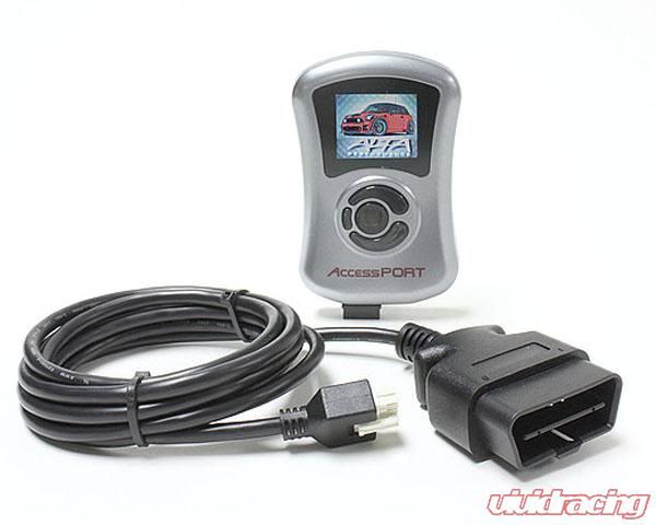
-Cobb AccessPort V2 (which uses a (below)OBDII wire instead of OBDII Dongle and USB cord)
![Image]()
-OBDII Spliter (J1962M to 2- J1962F Splitter) Amazon.com: Cable, J1962M to 2-J1962F, Splitter Cable, 1ft (145802): Automotive
![Image]()
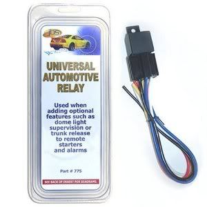
-Relay Amazon.com: A2C 775 Universal Automotive Relay: Automotive
![Image]()
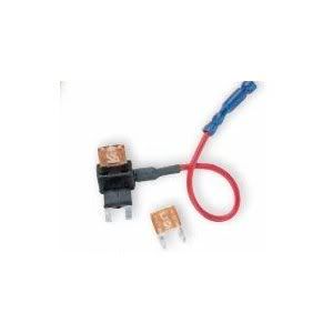
-HHH Add-A-Circuit Amazon.com: Bussmann BP/HHH ATM Add-A-Fuse: Automotive
![Image]()
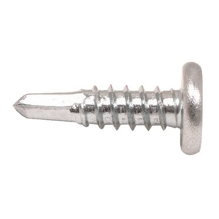
-Self Tapping Screw
![Image]()
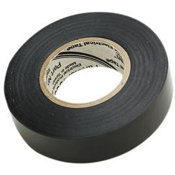
-Electrical Tape
![Image]()
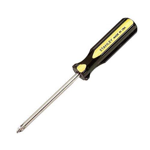
-Phillips Screwdriver
![Image]()
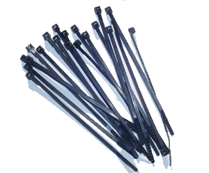
-Zip Ties
![Image]()
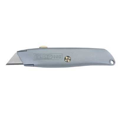
-Razor/Utility Knife
![Image]()
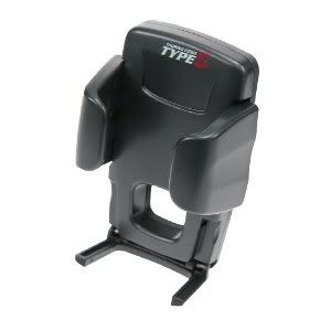
-Universal Holder or something similar
![Image]()
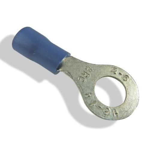
-Ring Style Crimp Connector
![Image]()
-Spare Wire
![Image]()
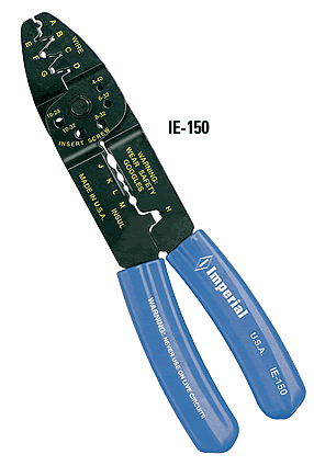
-Crimpers/Wire Cutters
![Image]()
STEP #1)
On your OBDII splitter choose a side that will be designated for the AP. This side we will be opening. Remove about an inch worth of insulation from the center of the cable you are working with.
STEP #2)
With the insulation removed and the wires inside visible, find the brown wire (connects to pin 5 - Signal Ground) and cut it. remove some insulation from both sides of the wire.
![Image]()
STEP #3)
On the brown wire hot side (side closest to the splitter) add a wire to connect to your relay. It will connect to Pin #30 (Blue)
STEP #4)
On the brown wire cold side (side closest to AP Connection) add a wire to connect to your relay. It will connect to Pin #87 (Yellow)
STEP #5)
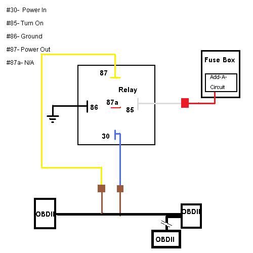
Tape everything back up, leaving no open wires. What you should have is the splitter with one side having 2 wires connected to the relay on Pins #30(Blue) and #87(Yellow).
STEP #6)
Prepare our ground wire for the relay. It connects to Pin #86 (Black). Add a Ring Style crimp connector on the other end of the wire for the chassis ground.
STEP #7)
Prepare the "Switch on" power for the relay. It Connects to Pin #85 (White). This will connect to the Add-A-Circuit. I used a 3a fuse in addition to the 10a i was replacing.
STEP #8)
Double check all your work, making sure there are no bare wires and you have good connections at all points where wires meet. The chart below shows how it should look in when you are finished (minus fuse box)
![Image]()
STEP #9)
Go to car. Remove the Driver Side lower dash (3 screws, 3 clips) and remove OBDII connector from panel (push tabs in, 4 in total. 2 on plastic that mounts OBDII connector and 2 on mount that hold it all on panel)
![Image]()
STEP #10)
Test AP. Plug AP OBDII into the relay side of splitter and see if it turns on. If it doesn't, Great. if it does turn on, then you didnt cut the proper wire in the splitter. Check the other side of the splitter now (without the relay) and your AP should turn on.
STEP #11)
Find a Place to mount your relay. I used a spot to the left of the fuse box, directly above the hood latch. There was an end of a bolt coming through from the other side that i hung the relay on and put a bolt on top to keep it secure.
STEP #12)
Create a Ground with your self tapping screw. There is a lot of metal under the dash that is suitable for the ground. I wanted to keep it as close to the relay as possible, so I tapped my screw in to the left of the hole for the screw that is above hood latch. It is possible to just use the hole above the hood latch as the ground by putting the ring connector on the screw as your put it back on.
STEP #13)
Connect the Add-A-Curcuit in the fusebox. I used slot #14 (rear wiper) as I have a sedan and it turns on with ignition.
STEP #14)
check all connections. plug in AP again. It should still be off. now turn your key to the on postion. does the AP come on? I hope so!
STEP #15)
Route wires out of the way. Route AP wire to where you wish to mount your AP. Secure all wire with zip-ties. Re-assemble lower dash (3 clips on top, 2 screws on bottom, 1 screw/pushpin on side) At this point you can push your other end of the splitter through where the OBDII connection used to be. (its a tight fit. i cut a little slice of plastic off with my utility knife and it went in)
STEP #16)
Using your Holder put your AP into place. Connect and Enjoy your AP that goes off when your key does.
Note: On the relay i used it had a wire to Pin #87a. this wire was red and it was not used.
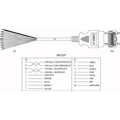
NOTE: Image below is what I used to determine which wire is which. Do Not Cut through the whole cable! only cut the brown wire. In testing to find out which wire was suitable to be used with the relay, First i tried #16-RED, did not work. Next was #4-BLACK, also no luck. Finally I try #5-BROWN and I achieve success.
![Image]()
PS: there are other things that you can do along these lines as well. Other things i thought of was putting a switch under the dash somewhere that connects to the reflash connectors. no fear of misplacing connectors. mount the switch in a hidden spot close to the green diagnostic connectors that way whenever you want to reflash you can hit the switch while your plugging in the green connectors.
Also i am not responsible for anything you mess up. use at your own risk
this will be worked on more and will get pics.
1st you will need a few things to get started. among these are:
-Cobb AccessPort V2 (which uses a (below)OBDII wire instead of OBDII Dongle and USB cord)
-OBDII Spliter (J1962M to 2- J1962F Splitter) Amazon.com: Cable, J1962M to 2-J1962F, Splitter Cable, 1ft (145802): Automotive

-Relay Amazon.com: A2C 775 Universal Automotive Relay: Automotive
-HHH Add-A-Circuit Amazon.com: Bussmann BP/HHH ATM Add-A-Fuse: Automotive
-Self Tapping Screw
-Electrical Tape
-Phillips Screwdriver
-Zip Ties
-Razor/Utility Knife
-Universal Holder or something similar
-Ring Style Crimp Connector
-Spare Wire

-Crimpers/Wire Cutters
STEP #1)
On your OBDII splitter choose a side that will be designated for the AP. This side we will be opening. Remove about an inch worth of insulation from the center of the cable you are working with.
STEP #2)
With the insulation removed and the wires inside visible, find the brown wire (connects to pin 5 - Signal Ground) and cut it. remove some insulation from both sides of the wire.

STEP #3)
On the brown wire hot side (side closest to the splitter) add a wire to connect to your relay. It will connect to Pin #30 (Blue)
STEP #4)
On the brown wire cold side (side closest to AP Connection) add a wire to connect to your relay. It will connect to Pin #87 (Yellow)
STEP #5)
Tape everything back up, leaving no open wires. What you should have is the splitter with one side having 2 wires connected to the relay on Pins #30(Blue) and #87(Yellow).
STEP #6)
Prepare our ground wire for the relay. It connects to Pin #86 (Black). Add a Ring Style crimp connector on the other end of the wire for the chassis ground.
STEP #7)
Prepare the "Switch on" power for the relay. It Connects to Pin #85 (White). This will connect to the Add-A-Circuit. I used a 3a fuse in addition to the 10a i was replacing.
STEP #8)
Double check all your work, making sure there are no bare wires and you have good connections at all points where wires meet. The chart below shows how it should look in when you are finished (minus fuse box)
STEP #9)
Go to car. Remove the Driver Side lower dash (3 screws, 3 clips) and remove OBDII connector from panel (push tabs in, 4 in total. 2 on plastic that mounts OBDII connector and 2 on mount that hold it all on panel)

STEP #10)
Test AP. Plug AP OBDII into the relay side of splitter and see if it turns on. If it doesn't, Great. if it does turn on, then you didnt cut the proper wire in the splitter. Check the other side of the splitter now (without the relay) and your AP should turn on.
STEP #11)
Find a Place to mount your relay. I used a spot to the left of the fuse box, directly above the hood latch. There was an end of a bolt coming through from the other side that i hung the relay on and put a bolt on top to keep it secure.
STEP #12)
Create a Ground with your self tapping screw. There is a lot of metal under the dash that is suitable for the ground. I wanted to keep it as close to the relay as possible, so I tapped my screw in to the left of the hole for the screw that is above hood latch. It is possible to just use the hole above the hood latch as the ground by putting the ring connector on the screw as your put it back on.
STEP #13)
Connect the Add-A-Curcuit in the fusebox. I used slot #14 (rear wiper) as I have a sedan and it turns on with ignition.
STEP #14)
check all connections. plug in AP again. It should still be off. now turn your key to the on postion. does the AP come on? I hope so!
STEP #15)
Route wires out of the way. Route AP wire to where you wish to mount your AP. Secure all wire with zip-ties. Re-assemble lower dash (3 clips on top, 2 screws on bottom, 1 screw/pushpin on side) At this point you can push your other end of the splitter through where the OBDII connection used to be. (its a tight fit. i cut a little slice of plastic off with my utility knife and it went in)
STEP #16)
Using your Holder put your AP into place. Connect and Enjoy your AP that goes off when your key does.
Note: On the relay i used it had a wire to Pin #87a. this wire was red and it was not used.
NOTE: Image below is what I used to determine which wire is which. Do Not Cut through the whole cable! only cut the brown wire. In testing to find out which wire was suitable to be used with the relay, First i tried #16-RED, did not work. Next was #4-BLACK, also no luck. Finally I try #5-BROWN and I achieve success.
PS: there are other things that you can do along these lines as well. Other things i thought of was putting a switch under the dash somewhere that connects to the reflash connectors. no fear of misplacing connectors. mount the switch in a hidden spot close to the green diagnostic connectors that way whenever you want to reflash you can hit the switch while your plugging in the green connectors.
Also i am not responsible for anything you mess up. use at your own risk
this will be worked on more and will get pics.